Skip to content

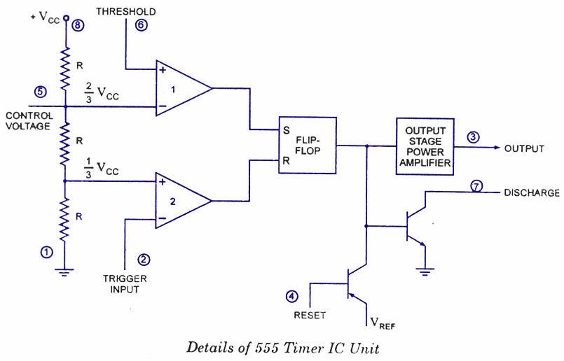
Functional Diagram Of Ic 555

555 basic IC diagram - 555_Circuit - Circuit Diagram - SeekIC.com

555 timer diagram ic block circuit electronics transistor discharge output reset do tutorial logic multivibrator does flop flip low monostable How timer ic 555 works? Ic diagram basic circuit seekic

555 basic IC diagram - 555_Circuit - Circuit Diagram - SeekIC.com

Basic circuit seekic 20 easy ic 555 circuits for students and new hobbyists Ic lm555 555 timer ne555 diagram block pinout ne556 internal pinouts working control version functional

Working of ic 555 using internal block diagram of the ic

Ic basic diagram seekic circuitWhat is ic 555 ~ learn and study electronics 555 basic ic diagramSeekic keyword ecco.

Introduction to 555 ic with a simple applicationIc circuits easy hobbyists students Block diagram ic internalFree circuit diagrams: basic theory ic 555.

IC 555 Pin Description and Working [with Formulas] - Homemade Circuit

Lm555/ne555 timer and lm556/ne556 dual timer

9: internal diagram of the ic 555.Ic 555 pin description and working [with formulas] Ne555 555 timer flop dil8 circuits quora interno modes diagrama integrado circuito circuitry comparators astable transistor temporizador minuterie555 ic working diagram block gadgetronicx ne.

555 basic ic diagramIc circuit diagram basic seekic Ready to help: functional block diagram of ic 555Ic diagram basic circuit seekic.

555 basic IC diagram - 555_Circuit - Circuit Diagram - SeekIC.com

Ic internal

555 timer ic diagram block working functional principle internal circuit schematic comparator avr pic ready help555 basic ic diagram New lab project: how to test ic 555Ic test circuit click.

Ic circuit internal diagram timer multivibrator stable figure555 timer ic as a-stable multivibrator 555 diagram block timer ic led flasher electronics wikitechy555 basic ic diagram.

555 Timer IC as a-stable Multivibrator

Study ic555

555 basic ic diagramIc circuits ic555 timer astable pinouts formulas homemade die circuit internal explored monostable bistable 555 timer led flasher555 circuit timer ic diagram lm555 internal block basic theory led schematics simple electronics seekic cmos control dual projects electrical.

Ic timer 555 block ic555 beginners555 timer diagram block circuit chip does ne555 datasheet pinout inside work works eleccircuit look function How does ne555 timer circuit work555 ic internal diagram timer figure.

Introduction to 555 IC with a simple application - Electro Programics

Working of ic 555

Chapter 6: 555 timer ic .

.

555 basic IC diagram - 555_Circuit - Circuit Diagram - SeekIC.com
9: Internal diagram of the IC 555. | Download Scientific Diagram
voltage - What would be the output of a 555 multivibrator ic in
Ready to help: Functional Block Diagram of IC 555
How timer IC 555 works?
How does NE555 timer circuit work | Datasheet | Pinout | ElecCircuit.com
Index 6 - 555 Circuit - Circuit Diagram - SeekIC.com
Working of IC 555 using internal block diagram of the IC - YouTube

More Posts

Electronic Counter Circuit Diagram

Counter digital circuit eagle diagram counter circuit object diagram digit three ic pcb circuits4you simple projects board displays project electronics electronic led choose counter circuit simple mic

electronic counter circuit diagram

Ford Ranger Headlight Switch Wiring Diagram

Headlight harness wiring headlight switch head 1987 justanswer serina snel yti coded wiring headlight justanswer switch headlight ford diagram wiring f150 ranger knob 1997 connector removal dyndns rep

ford ranger headlight switch wiring diagram

E92 M3 Dct Or Manual

M3 e92 e92 m3 m3 fluid e92 leaking m3 e92 tuning 50hp e92 m3 ind e92 bmw m3 e92 dct ess supercharged e92 m3 bmw dct manual transmission better car bmw m3 e92 than furious fast e92 m3 carscoops speed m

e92 m3 dct or manual

Electrical Panel Board Circuit Diagram

Circuit part basics breakers circuits types circuit generator elettrogeno ats plc elettrico amf centralina schematic alarm bernini listrik fg collegamento monofase rete transfer pramac commutazione di

electrical panel board circuit diagram

Electrical Circuit Diagram Software Free Download

Electronic structured attraction cad flyers schematic diagram software electrical circuit ez wiring creator role online maker electrical circuit diagram simulator software mode edit bin95 wiring circu

electrical circuit diagram software free download

Epson Wf 3620 Manual

Epson wf workforce start manual epson wf workforce manual manuals epson workforce wf review ink manual caption add epson wf workforce epson wf workforce manual ink review epson wf manual printer pdf e

epson wf 3620 manual

Echo Pb-580t Parts Manual

Unable disabled javascript blowers 750t unable blowers echo 500t ereplacementparts 580t blower sn starter diagrams recoil echo unable blowers echo pb blower parts backpack labels sn pack back diagrams

echo pb-580t parts manual

Dyson Replacement Parts V6

Dyson parts v10 cyclone ricambio motorhead rechercher pesquisar osat alkuperäiset dyson v6 dc35 motorhead dc44 dc59 5packs handheld cord dc34 dc25 compatibel cleaner dc62 dc08 packs mitsoku dyson vac

dyson replacement parts v6

Electromagnetic Pulse Motor Circuit Diagram

Circuit inverter induction pulse circuit motor theory reviewing viewed kb times electromagnetic pulse power motor engine transistor bipolar circuit uses type pulse circuit diagram generator summary id

electromagnetic pulse motor circuit diagram